Problem B: Boolean Network Steady States
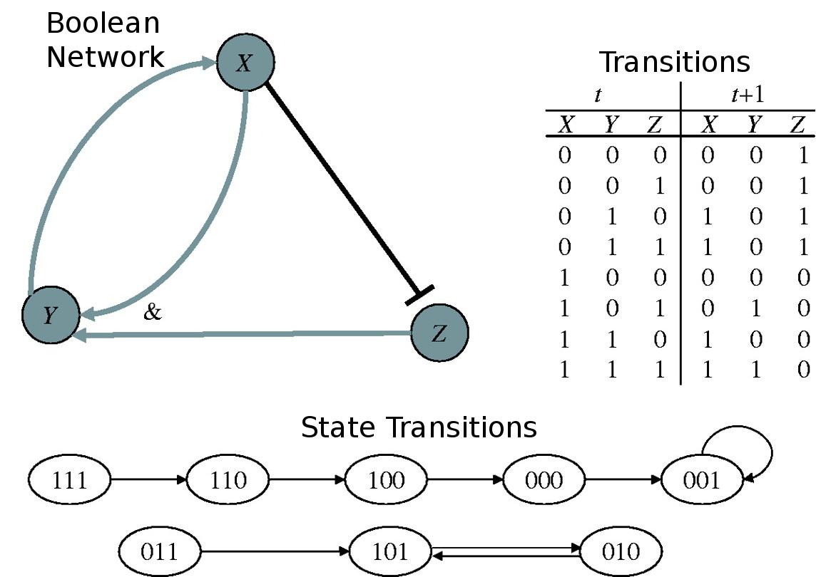
 Boolean networks are often used as a crude simulation of biological systems. They represent the relationship between genes and assume that each gene is either on or off. The state of each gene is determined by a boolean combination of the states of other genes in the network. The following is a representation of the boolean network depicted in the image.
In synchronous boolean networks, the state of each variable in the next time step is dependant on the state of the variables in the current time step. The following is an example of the states of each variable assuming that each gene in the network was initially on.
| | 0 | 1 | 2 | 3 | 4 |
| |
| X | 1 | 1 | 1 | 0 | 0 |
| Y | 1 | 1 | 0 | 0 | 0 |
| Z | 1 | 0 | 0 | 1 | 1 |
In this case, 0 0 1 is a steady state, in the sense that it produces the exact same state in the next time step. Your goal is to find all steady states in a boolean network.
Task
You are given the description of a boolean network and your goal is to count the number of steady states in the network. Each boolean equation is given in postfix notation.
Input
Your input starts with a line with the number of genes N followed by N lines, one for each of the 0, ⋯, N−1 genes, with an integer F standing for the number of elements of the boolean equation and followed by the boolean equation in postfix notation where the genes are numbered from 0, ⋯, N−1. Recall that in postfix notation every operator follows its operands. The sample input section includes a detailed example.
The following symbols represent the boolean operators.
| Symbol | Boolean operator |
| |
| * | AND |
| + | OR |
| − | NOT
|
Output
The output is a line with a number indicating the number of steady states in the network.
Constraints
| 2 ≤ N ≤ 15 | Number of genes in the network |
| 2 ≤ F ≤ 100 | Number of elements in each boolean equation
|
Input Example 1
3
1 1
3 0 2 *
2 0 -
Output Example 1
1
Explanation of Example 1
This input corresponds to the figure in the problem statement.
Input Example 2
5
3 1 2 +
8 0 2 + 3 4 * - +
4 3 4 * -
9 0 1 * - 2 4 * - +
3 0 1 +
Output Example 2
2
Explanation of Example 2
This input corresponds to a boolean network with five genes, each having the following equations:
| g0 | = | g1 ∨ g2 |
| g1 | = | (g0 ∨ g2) ∨ ¬ (g3 ∧ g4) |
| g2 | = | ¬ (g3 ∧ g4) |
| g3 | = | ¬ (g0 ∧ g1) ∨ ¬ (g2 ∧ g4) |
| g4 | = | g0 ∨ g1
|
|
This document was translated from LATEX by
HEVEA.
 Boolean networks are often used as a crude simulation of biological systems. They represent the relationship between genes and assume that each gene is either on or off. The state of each gene is determined by a boolean combination of the states of other genes in the network. The following is a representation of the boolean network depicted in the image.